Electrical Hardware
The control circuitry that drives this display was created from scratch. Individual circuits were designed to allow the software on the PC to ultimately turn on and off individual channels. These circuits were each laid out on separate printed circuit boards and ordered from a board manufacturer. Once the boards arrived, each was assembled and tested. In all, 4 different boards were created for this display.
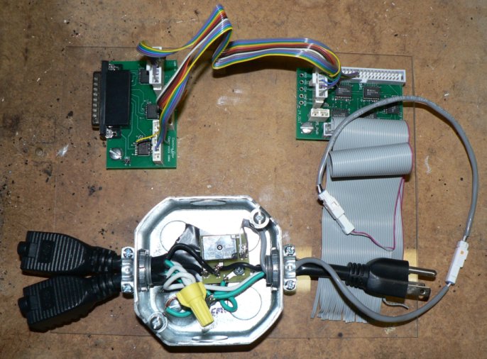
The original hardware consisted of three custom printed circuit boards. These boards are shown above. The PC talks to an isolation board (upper left) which is connected to expandable relay drive boards (upper right). Ribbon cable connects these signals to individual relay boards (lower left). Each relay board was packaged into an individually control box with cables for power input and output. A fourth board was later created to support control of multiple local channels.
The first board in the picture was designed to be connected to the computer by a parallel cable. The purpose of this board was to electrically isolate the PC from the relays. The computer did not power the relays. A separate power supply was used. The isolation board translated the signals from the computer power supply to the other external supply.
The second board was responsible for decoding the serial communication. Multiple copies of this board were used to fan out the serial data patterns into multiple separate signals. Each board supported 40 channels. The resulting signals could then individually be routed to a relay. These boards were designed to support chaining them together to support additional control channels.
The final board was the relay board. It contained the relay and related protection circuitry. Each channel had its own miniature board. These boards were packaged inside an electrical ceiling box with cords to supply and connect power. The mechanical housing was custom designed and assembled using readily available and inexpensive materials.
Custom Display Letters
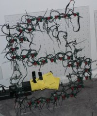
Most of the Christmas lights were purchased on clearance after Christmas. The one exception was the 18 by 24 inch letters. We custom designed these letters for our display. Each letter consisted of 1 acrylic sheet (plexiglass) with framing around it for support. A grid of 1/2 inch holes were drilled in the plexiglass to create a 12x9 array of blocks. Each block had 4 holes to support 4 different colored bulbs. Only 3 of the holes were actually used for red, green, and white. The letters were created by inserting spliced strands of LED lights into the appropriate holes. Each bulb is manually secured using two zip tie wraps.
To support these letters, a fourth circuit board was later added to control multiple localized channels. Four of these boards were used, each containing 10 relays, to control colored 18 x 24 inch letters. Without these separate boards, 41 control boxes would have been required to control the letters. This fourth board avoided this and eliminated the need for more expensive individual mechanical housing and cabling.